LearnDesigning for 3D printing
How to design for 3D printing: from idea to a part that fits
The design rules with real numbers (walls, overhangs, holes, tolerances, orientation) and two ways to get from idea to a part that fits this afternoon.
· 11 min read
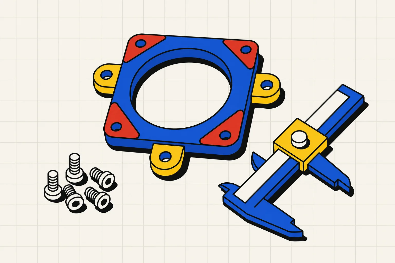
Design for the way the printer builds the part: in layers, from the bed up, through a 0.4 mm nozzle. Get the numbers below right and the rest is choosing a tool and printing a test.
To design a part for 3D printing, start from the printer's limits. Walls should be at least 0.8 mm on a standard 0.4 mm nozzle, so two perimeters can print. Any face that leans out more than 45 degrees from vertical needs support, so orient the part to keep overhangs under that angle. Bridges over 10 to 15 mm sag. Vertical holes print 0.1 to 0.4 mm under size, so draw an M3 hole at 3.2 to 3.4 mm rather than 3.0. For parts that fit together, leave about 0.1 mm for a press fit, 0.2 mm for a snug slide, and 0.3 mm or more for free movement, then print a small test before the real part. Layers are the weak direction, so put the load in the plane of the layers. Add a 0.5 mm chamfer at the bottom edge for elephant's foot, and fillet vertical edges. Then export STL and slice.
You have a Bambu, a Prusa or a Creality. You have printed a hundred other people's files. Now you want a bracket nobody has made, with your hole pattern and your dimensions. This is the page for that step.
The rules, with the numbers
Every rule below comes from one picture: the printer lays down a hot line of plastic about 0.4 mm wide and 0.2 mm tall, one layer at a time, and each layer has to sit on something.
Wall thickness
With a 0.4 mm nozzle, two perimeters is 0.8 mm, and that is the minimum Wikifactory gives for FDM: at least two times the nozzle diameter. UltiMaker quotes 0.5 mm, but on its smallest 0.25 mm nozzle, and says the minimum rises with nozzle size. So the floor is 0.5 to 0.8 mm depending on nozzle. For anything structural, go thicker, and add perimeters rather than infill. Rahix's guide points out that bending stress lives at the surface of a part, so extra perimeters do more for strength than a higher infill percentage.
Overhangs and the 45 degree rule
Each layer can stick out a little past the one below. Up to 45 degrees from vertical, FDM parts are self-supporting, and both UltiMaker and Wikifactory give that number. Wikifactory adds that decent quality is possible up to 60 degrees with the right material and cooling, and that anything above 60 degrees needs support. Bambu Lab's test model notes say the same from the other direction: angles below 30 degrees from the bed are often difficult.
Supports cost time and leave marks, and Rahix notes that supported surfaces have much worse tolerances than the rest of the part. Design them out: put the flat face on the bed, chamfer the underside of a ledge at 45 degrees instead of leaving it square, or split the part in two.
Bridges
A bridge is a flat span between two supported points. UltiMaker says most basic filaments bridge a 10 mm gap without support, and that it has printed 25 mm bridges with Tough PLA and tuned cooling. Wikifactory sets the limit at 15 mm. Bambu Lab's benchmark calls 40 to 50 mm a very good result on a tuned modern printer.
Keep bridges under 10 to 15 mm and they will work on any printer. For a bigger span, add a rib underneath or turn the bridge into a shallow arch.
Holes print small
A vertical hole drawn at 3.0 mm comes out somewhere between 2.6 and 2.9 mm. Wikifactory explains why: the extruded plastic is squashed against the previous layer and spreads sideways. Rahix adds a second cause: the nozzle drags the line behind it, so circles come out small, and the seam can push the error to 0.4 mm. Wikifactory's fix is to test, then add the undersize back into the model, for example 0.2 mm on a 2 mm hole.
Two ways to handle it:
- In the model. Draw the hole larger. A Prusa forum regular uses 5.2 mm for a 5 mm screw to get a snug fit, and 5.3 to 5.4 mm for a loose one. Scaled to M3, that is 3.2 mm snug and 3.4 mm loose. If you want the screw to bite into the plastic instead of using a nut, Wikifactory suggests 2.8 mm for a 3 mm screw.
- In the slicer. Bambu Studio has an XY hole compensation setting. The wiki's method is a calibration print: set it to 0, print, find which hole fits the screw, enter that value. The hole grows by twice the compensation, and it is per filament, so redo it when you change spools.
UltiMaker adds a floor: holes under 2 mm tend to fill in, and if you need an accurate hole, print it small and drill it. Horizontal holes have a different problem: the top of the circle is an overhang. Rahix's fix is a teardrop with a 90 degree point at the top, or a flat roof for larger holes.
Tolerances: press fit, slip fit, clearance
The sources agree on the idea and disagree on the numbers, which depend on the printer and the filament.
| Fit | Markforged (diametral) | Prusa forum (per side) | Others |
|---|---|---|---|
| Press fit, needs force | 0.00 to 0.05 mm | 0.1 mm tight | Rahix: undersize crush ribs 0.2 mm, oversize bore 0.4 mm |
| Close or snug, hand assembly | 0.05 to 0.10 mm | 0.2 to 0.25 mm, some drag | Wikifactory: 0.3 mm between interlocking parts |
| Free, slides or rotates | 0.10 to 0.20 mm | 0.3 to 0.4 mm loose | Sinterit: 0.2 to 0.5 mm, or 0.4 to 0.6 mm on its tolerances page, so even one vendor varies; UltiMaker: 0.6 mm gap for parts printed together |
Markforged's numbers are tight because they come from an industrial printer. The Prusa and Wikifactory numbers are what a hobby machine delivers. Rahix's rule of thumb for a calibrated 0.4 mm nozzle at 0.2 mm layers is plus or minus 0.1 mm per surface, so a clearance fit needs a gap larger than twice that. Formlabs is the pessimist at plus or minus 0.5 percent with a 0.5 mm floor, which covers untuned machines.
Whatever you pick, test it. Markforged calls this a unit test: isolate the fitting feature, print it small, try three clearances, and put the winner back in the model. The Prusa thread has an honest ending. The person printed a batch of eight and found some pairs fit well and others were loose. That is FDM. A design that tolerates it beats one that assumes precision.
Orientation and layer direction
A printed part is strong along a layer and weak between layers. Rahix cites tests showing roughly three times more strength in the ideal orientation. Markforged states it as a rule: work out how the part is loaded and design it so the largest forces run in the XY plane.
For a bracket, that means the leg that carries the load prints lying flat, or the corner gets a gusset so no load pulls straight across a layer line. If no orientation works, split the part and print each piece its own way. Rahix's joint of choice is a dovetail. Markforged's default orientation is the largest flat face on the bed, unless strength says otherwise.
Fillets and chamfers
Fillets on inside corners spread stress and stop cracks. Rahix and Markforged both make the point, and Wikifactory adds that even a 2 mm fillet on an outside corner cleans up the surface because the print head no longer has to stop dead at 90 degrees.
Rahix's rule: chamfers on edges parallel to the print surface, fillets on edges vertical to it. A fillet on a horizontal edge starts as a near-flat overhang and prints badly. A chamfer is a constant 45 degrees and prints cleanly. Wikifactory agrees on the bottom edge specifically: no fillets there, because they increase warping, but a small chamfer helps.
Elephant's foot
The first layer gets squashed harder than the rest, so the bottom edge bulges out. UltiMaker says it is rarely visible but it decreases the tolerance of functional parts. The fix from both UltiMaker and Wikifactory is a small 45 degree chamfer on the bottom edge, and 0.5 mm is plenty. Wikifactory adds the process causes: a nozzle too close to the bed, or a bed too hot for PLA.
Worked example: a bracket for a 40 mm fan
Say you want to hang a 40 mm fan off the side of a shelf to cool a Raspberry Pi. A 40 mm fan has four mounting holes on a 32 mm square, and they take M3 screws.
Here is the part, with the rules applied:
- Plate: 46 by 46 mm, 3 mm thick, so any wall around a hole is at least 3 mm of plastic.
- Fan holes: four holes on a 32 mm square, drawn at 3.4 mm: 3.0 mm for the screw plus 0.4 mm because holes print small and the screw only needs to pass through.
- Airflow opening: a 38 mm hole in the middle, so the fan is not blowing into a wall.
- Mounting leg: a second plate at 90 degrees, 46 by 30 mm, 3 mm thick, with two 4.4 mm slots for M4 wood screws. Slots, because Rahix's advice is that oblong holes let you slide the part into alignment.
- Gusset: a triangular rib, 3 mm thick, 20 mm each way from the fan plate to the leg. Without it the corner is one layer line under bending load.
- Corner: a 2 mm fillet on the inside of the L so stress does not concentrate, and 2 mm fillets on the vertical outer corners.
- Orientation: fan plate flat on the bed. The leg stands up as a 3 mm wall, the gusset is a 45 degree triangle and needs no support, and the fan's load pulls along the layers of the plate.
- Chamfer: 0.5 mm at 45 degrees on every bottom edge.
Print it, screw the fan on, and if the M3 screws are tight in 3.4 mm holes, bump the hole to 3.5 mm or set 0.1 mm of XY hole compensation in Bambu Studio and print again. That is the whole loop. The Type Parts bracket generator builds this exact shape from sliders if you would rather not draw it. <!-- link /make/bracket when it ships -->
From idea to part in an afternoon
Two routes get you from a sketch to a file in the slicer before dinner.
Route 1: model it yourself in Tinkercad or Fusion
Tinkercad runs in the browser and works by stacking and subtracting blocks. The bracket above is two boxes, a cylinder subtracted for the opening, four small cylinders for the holes, and a wedge for the gusset. An hour, the first time. What Tinkercad will not do is remind you that the holes should be 3.4 mm. You hold every rule in your head, and you find out at the printer.
Fusion is the step up: sketches with real dimensions, one-click fillets and chamfers, and a parameter table so you can change the fan size later. It costs a weekend to get comfortable, and the free tier has been shrinking. Our guide to free CAD software for 3D printing lays out what each free option allows, and easy CAD for 3D printing ranks the beginner routes by hours to first part.
Either way, export STL for the slicer. If you might ever edit the part in another tool or send it to a machine shop, keep a STEP too. The difference is covered in STL vs STEP.
Route 2: describe it, and let the checks enforce the rules
The other route is to write the part down in words with its real dimensions and let a text-to-CAD tool build it. The description for the bracket is the bullet list above, more or less verbatim.
On Type Parts, the model writes a build123d script with a parameter block at the top and a set of checks for wall thickness, hole sizes and fit. A sandbox runs the script. If a check fails, or the geometry does not build, the error goes back to the model and it tries again, up to four rounds. You see the checklist, so you know the walls are over 0.8 mm and the holes are not drawn at 3.0 mm before you download anything.
The parameters become sliders. Tuning the hole from 3.4 to 3.5 mm after a test print is a slider move and a re-export. Export STL for the slicer, or STEP on the Maker or Pro plan if you want the part editable later.
The first part is free with no account, and signing up gives you 4 credits. Plans are $15 a month for Hobby, $49 for Maker and $119 for Pro. The rules above still apply, and you still print a test for the fit. The checks just catch the 3.0 mm hole and the 0.6 mm wall before the printer does.