LearnStart here
Text-to-CAD: what it is, how it works, and which tools actually make parts
How text-to-CAD turns a sentence into a CAD model, the three ways tools generate geometry, and an honest comparison of what each one can export.
· 16 min read
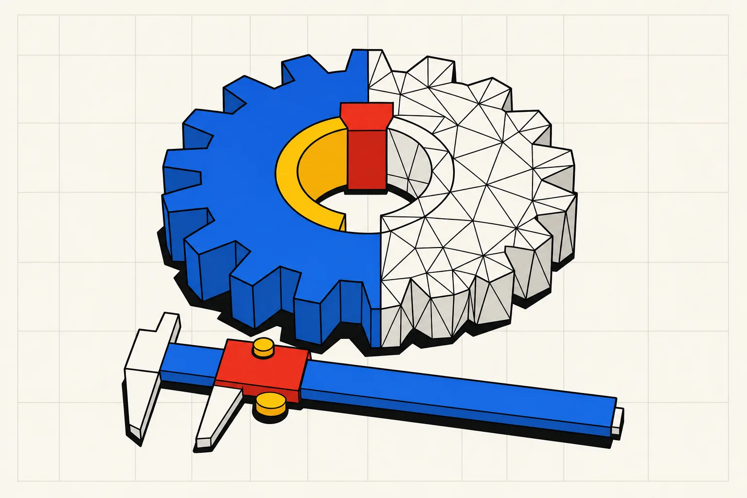
Text-to-CAD is software that turns a written description of a part into a 3D CAD model. You type something like "a 24-tooth spur gear, module 2, 8 mm bore, 10 mm thick" and the tool returns geometry you can download as STL or STEP. Under the hood, a language model reads the sentence, works out which features it implies (a gear profile, a bore, a thickness) and produces them in one of three ways. A trained network can output a triangle mesh directly. The model can write a script in a CAD language such as OpenSCAD or build123d, which a solver then runs. Or the model can drive a boundary-representation (B-rep) engine that builds exact surfaces. The better tools run the result through checks and feed failures back to the model before you see anything. The approach decides the output: meshes look right but carry no dimensions, while code and B-rep output stays parametric, so a bore can be changed afterwards.
What text-to-CAD means, and what it does not
In the mechanical world, CAD means a model with exact geometry: a hole is a cylinder of a known diameter, a wall has a known thickness. Text-to-CAD keeps that definition and changes the input. Instead of sketching and extruding in Fusion or FreeCAD, you describe the part and a model does the sketching.
Two neighbouring categories land in the same search results.
Text-to-3D tools like Meshy, Tripo and Hunyuan 3D generate a textured triangle mesh from a prompt. Meshy calls itself "a free AI 3D model generator that turns text or images into ready-to-use 3D models in under a minute", and it exports STL, OBJ and 3MF straight to a slicer. It is built for dragons and busts. What it cannot give you is an 8.00 mm hole. The difference is the subject of AI 3D model generators for functional parts.
AI drawing generators like OpenArt produce 2D images that look like CAD drawings. Xometry tested one on a manifold block and got "photorealistic concept art that looked impressive but had no engineering utility". If a search for AI CAD generator<!-- link /ai-cad-generator when it ships --> lands you on a tool that exports PNG, you are in this category.
Text-to-CAD proper produces a solid with dimensions. This guide is about that.
How text-to-CAD works: from prompt to file
Every text-to-CAD tool runs some version of the same four stages. Leo AI's explainer lays them out.
- Parsing. The model pulls out what matters: part type, dimensions, counts, patterns. "Four M5 holes on a 60 mm bolt circle" becomes a hole diameter, a count and a pattern diameter.
- Intent mapping. Each phrase becomes a modelling operation. A flange is a profile and an extrude. A bolt circle is a circular pattern of cuts. This is where a vague prompt goes wrong: "bracket" can mean an L, a U or a Z, and the model picks one.
- Geometry generation. The operations are executed to make a solid. The three approaches in the next section diverge here.
- Output. The geometry is written to a file. Which files you can get depends on stage 3.
Most explainers skip what happens when stage 3 fails, and it fails often. A tool that hands you the raw result is a demo. A tool that runs the output, tests it and sends the errors back to the model is a product.
The three ways tools generate geometry
Same prompt, three very different files.
Mesh generation
A network trained on 3D shape datasets outputs a triangle mesh directly from the prompt. This is how Meshy, Tripo and Hunyuan 3D work.
You get a surface made of triangles, usually a lot of them. Meshy says its models "come out watertight and manifold", which is the property a slicer needs.
You do not get dimensions. The mesh has no idea that one ring of triangles is supposed to be a 6.2 mm hole for an M6 bolt. You cannot ask for the hole to be 0.2 mm larger. You cannot export STEP, because there are no surfaces to export, only facets. Editing means pushing vertices in Blender. That is why how to edit an STL file is a much-searched question with an unsatisfying answer.
Code generation
A language model writes a script in a CAD language, and a solver runs the script. The languages are OpenSCAD, CadQuery, build123d, and Zoo's KCL.
OpenSCAD is the oldest and most familiar. The project calls itself "something like a 3D-compiler that reads in a script file that describes the object". Every dimension in the file is a variable, which is why makers have used it for parametric parts for years. build123d and CadQuery are Python libraries on the OpenCascade kernel. They do the same job with B-rep geometry underneath, so the result exports STEP with true fillets, where OpenSCAD only produces meshes.
Code generation has one large advantage: the output is parametric by construction. The script has a tooth_count variable because the model wrote one. Change it, re-run, and you have a new gear with its bore and keyway still in place. That is all a slider on a text-to-CAD tool is: a re-run of the script with a new value.
It has one large weakness, and Leo AI names it: "LLMs still make coding errors that produce invalid geometry." A script can fail to run, or run and produce two bodies that do not touch, or build a wall 0.4 mm thick where the printer needs 1.2. ChatGPT will write OpenSCAD for you today, and can ChatGPT create a CAD file shows what happens when it does. It writes plausible code and cannot run it, so you become the sandbox.
Direct B-rep generation
A model outputs CAD geometry directly, as a feature tree or a parametric sequence, into a B-rep kernel. Boundary representation is how SolidWorks, Fusion, Onshape and FreeCAD store models: exact faces, edges and vertices. Zoo's launch post made the distinction plainly. Text-to-3D tools "generate meshes so if you were to import that into an existing CAD program, it would just be one large amorphous blob and not editable in any useful way", whereas Zoo generates B-rep surfaces "so you can import a STEP file from Text-to-CAD into any existing CAD program and edit it".
The research version is Microsoft Research's CADFusion, published at ICML. It trains a language model on CAD "parametric sequences" (sketches and extrudes), then alternates that with a visual feedback stage that scores the rendered result. The code is on GitHub.
In practice the line between code generation and direct B-rep has blurred. Zoo's Zookeeper agent generates inside Zoo's engine, with "engine-level tools that let the agent inspect, snapshot, and debug geometry", and the result exports as KCL. Type Parts does the same with build123d. The distinction that still matters is whether the kernel underneath is B-rep or mesh.
Mesh, code and B-rep are the three ways a text-to-CAD tool can turn a prompt into geometry, and they produce different files. Mesh generation (Meshy, Tripo, Hunyuan 3D) uses a network trained on 3D shapes to output triangles directly. The result prints well for figures but has no dimensions to edit and cannot export STEP. Code generation has a language model write a script in OpenSCAD, CadQuery, build123d or KCL, then runs it. The output is parametric because every dimension is a variable in the script, but the model can write code that fails or builds the wrong shape, so a good tool runs and checks the script before showing it. Direct B-rep generation, used by Zoo and in research systems such as Microsoft's CADFusion, produces exact faces and edges in a CAD kernel, which opens in Fusion or SolidWorks as an editable solid. For a functional part, code or B-rep output is the right choice.
Why parametric output matters for functional parts
A decorative print only has to look right. A functional part has to fit something that has its own dimensions.
The build123d documentation puts reusability first: parametric models "can be easily modified by changing a set of parameters, such as the length or width of an object, rather than having to manually edit the geometry." Three cases where that pays off.
The first print is 0.3 mm off. Every FDM printer shrinks holes by its own amount. A parametric part has a bore parameter. You move it from 8.0 to 8.3, rebuild, reprint. A mesh from a text-to-3D tool has a ring of triangles and no bore.
The part is a family. A bracket<!-- link /make/bracket when it ships --> with a different hole pattern for each shelf. A spool holder<!-- link /make/spool-holder when it ships --> for a 200 mm spool and a 750 g one. A gear<!-- link /make/gear when it ships --> with 20 teeth and another with 36 that has to mesh with it. One description with parameters is the whole family. OpenSCAD users have always known this. Tinkercad users discover it the hard way when one dimension has to change in a model built from stacked blocks; see Tinkercad alternatives.
The checks depend on the dimensions. Wall thickness, clearance between a shaft and a bore, minimum feature size for the nozzle. These are rules with numbers, and they can only be enforced when the model knows its own numbers. The rules are in how to design for 3D printing. A parametric model runs them on every rebuild. A mesh cannot run them at all.
Leo AI calls the distance between generated output and production CAD "the parametric gap" and concludes that most text-to-CAD output "is not production-ready". That is true of mesh output and of unchecked code.
Where the model goes wrong, and what a verification loop does about it
Language models are good at writing CAD code and bad at knowing whether it worked. Three failures show up over and over. The script does not run: a fillet radius larger than its edge. The script runs and builds the wrong thing: the keyway on the outside of the gear, or two bodies that were meant to fuse and did not, so the slicer sees two shells. The part is right and unprintable: a 0.5 mm wall, an overhang with nothing under it.
The fix for all three is the same. Run it, check it, feed the result back. Anthropic's guide to building agents says an agent should "gain ground truth from the environment at each step (such as tool call results or code execution)", with "stopping conditions (such as a maximum number of iterations)" so the loop ends, and that feedback loops work best "when we have clear evaluation criteria". CAD has unusually clear criteria: a solid either has one body or it does not. A May 2026 paper introduces CADTests, "executable software tests that verify whether a generated CAD model satisfies the geometric and topological requirements of the input prompt", and reports that using them to guide generation yields "simple baselines that surpass performance of current methods". The checks are worth more than a bigger model.
Type Parts is built as that loop. The model writes a build123d script with a parameter block and a checklist for the part, a sandbox runs it, errors and failed checks go back to the model for up to four rounds, and you see the checklist with what passed and what failed before you download. Sliders re-run the script with no model in the loop, which is why moving them is free and immediate. Other tools have converged on the same shape: Zookeeper debugs geometry mid-generation, and the open-source text-to-cad skills library ships a check that "measures mesh printability per process: wall thickness, overhangs, support volume, and build orientation".
The tools compared
These are the tools that rank for text-to-CAD searches plus the open-source options people ask about. Prices are USD, from each vendor's pricing page or from Xometry's test where noted, and they change often. "Parametric after generation" means you can change a dimension without re-prompting.
| Tool | How it generates | Files you get | Parametric after generation | Free tier | Paid from | Best for |
|---|---|---|---|---|---|---|
| Zoo Design Studio (Zookeeper) | Agent generates in Zoo's B-rep engine, exports KCL | STEP, STL, OBJ, GLB, FBX, KCL | Yes, KCL code and sliders | 20 minutes of Zookeeper time per month | Plus $20/month, Pro $99/month | Mechanical parts in a desktop CAD app |
| TextoCAD | Browser tool; returns an editable model with sliders and a feature tree (method not published) | STEP, STL | Yes, sliders | 2 generations after sign-in; slider edits and exports free | Paid plans, prices not on the public page | Simple single parts in the browser |
| AdamCAD | Code generation with OpenSCAD export, as tested by Xometry | STL, SCAD | Yes, parameter list | Free tier as tested | $9.99/month (per Xometry) | Quick parametric concepts; adam.new now pitches an engineering agent for existing CAD |
| CADScribe | Not published | STEP, STL | No editing | 10 prompts | $4.99/month (per Xometry) | One simple part from a short prompt |
| Meshy | Mesh generation | STL, OBJ, 3MF, FBX, GLB | No | 100 credits per month | Pro $20/month for 1,000 credits | Figures, game assets, decorative prints |
| ChatGPT or Claude with OpenSCAD | Code generation; you run the code yourself | SCAD, then STL from OpenSCAD | Yes, if you edit the code | Free chat tiers | Chat subscriptions | People who can read and fix code |
| text-to-cad skills (GitHub, earthtojake) | Code generation inside Claude Code or Codex, open source | STEP, STL, 3MF, GLB | Yes, the source lives in your repo | Free, open source | Your own model costs | Developers already running a coding agent |
| CADFusion (Microsoft Research) | Trained LLM outputs sketch-extrude sequences | Parametric sequence, code on GitHub | In principle | Free, research code | None | Research and experiments |
| Type Parts | Model writes a build123d script with a parameter block, sandbox runs and checks it, up to 4 rounds | Preview free; STL on Hobby, STEP on Maker and Pro | Yes, sliders re-run the script | 1 part with no account, 4 credits at signup | Hobby $15/month for 25 credits | Functional parts and assemblies of up to 4 parts, for printing or CNC |
Notes the table cannot hold.
Xometry ran a cylinder, a 24-tooth gear and a manifold block through seven tools on their free tiers. Zoo "delivered accurate and editable 3D models" for the cylinder but "failed to produce an accurate model" for the gear and could not generate the manifold. AdamCAD got the cylinder and gear right and produced the manifold "in a simplified form". Their verdict: "The biggest limitations across the board? Lack of control, inconsistent file exports, and minimal support for complex assemblies or functional constraints." Tools have shipped updates since. The best text-to-CAD tools runs the same ten parts through each of them.
Zoo's free plan is measured in Zookeeper minutes rather than parts, and its pricing page says the individual plans train on your data unless you opt out.
Type Parts is the tool this site belongs to, so read that row as the vendor's description. One credit is one part or one change asked for in chat; questions, retries and slider moves cost nothing. Maker at $49 per month gives 80 credits and STEP export, Pro at $119 gives 250, and a 25-credit top-up is $15 with no subscription. The full breakdown is on the pricing page.
STL, STEP and what the shop wants
STL is a mesh: triangles and nothing else. Every slicer reads it and it is all a printer needs. Any tool can export it, including mesh generators.
STEP is the exact B-rep geometry. It opens in Fusion, FreeCAD, SolidWorks and Onshape as a solid you can keep working on, and it is what a CNC shop asks for, because the machinist needs real cylinders and real fillets for tool paths. Only tools with a B-rep kernel can produce it. A mesh generator cannot, and no converter fixes that properly. What is a STEP file covers the format, and STL vs STEP covers which to export when, including 3MF.
For CNC the bar is higher than for printing. CAD for CNC is about what a machinist expects in the file you send.
Open-source text-to-CAD, in three forms
The most complete is the text-to-cad skills library on GitHub, "a library of agent skills for generating, inspecting, sourcing, slicing, and handing off CAD" for coding agents. Its CAD skill works "from plain-language or image requests, with STEP as the main output along with options to export to STL, 3MF and GLB", and installs into Claude Code or Codex with one command. You bring your own model subscription and your own terminal. Pick it if you already live in a coding agent and want the scripts in your repo.
Zoo's original Text-to-CAD UI is open source, though the model behind it is hosted. CADFusion is research code, not a tool. OpenSCAD is free software and any language model can write it, the zero-cost route if you are willing to be the compiler and the test suite. OpenSCAD vs FreeCAD vs text-to-CAD walks through that trade with the same gear built three ways.
When text-to-CAD beats learning Fusion, and when it does not
Fusion for personal use is free "for personal, non-commercial projects only", for individuals "generating less than $1,000 USD annually". That is a good deal and a real skill. The question is whether the parts you need are worth the weekend it takes to get competent.
Text-to-CAD wins when the part is simple and specific. A bracket with your hole spacing, a knob for a 6 mm D-shaft, a phone stand<!-- link /make/phone-stand when it ships --> at your tilt. You know the numbers and the geometry is a few features. Describing it takes a minute. Modelling it takes ten minutes if you know Fusion and an afternoon if you are learning. Leo AI objects that a precise prompt "takes almost as long as creating the sketch in CAD software". For an engineer at a workstation that is often true. For a maker who has never opened a sketch, it is not.
Text-to-CAD wins when you need the part in several sizes. The second and third variants are a slider move.
Text-to-CAD wins when your Fusion licence is the problem. The personal-use tier keeps its limits, and people who sell a few prints cross the revenue line. Fusion 360 alternatives covers that situation, and free CAD software for 3D printing lists what each free tier really allows.
Fusion wins when the part is complex. Assemblies with dozens of parts, lofted surfaces, sheet metal with bend tables, anything that needs a drawing with GD&T callouts. No tool in Xometry's test built the manifold block with internal channels as specified; the best result was a simplified version. Leo AI is right that "complex surfaces, lofted features, and multi-body configurations are either impossible or fragile" in code-generated CAD today. Type Parts caps assemblies at four parts for this reason.
Fusion wins when you would rather think in geometry. Some people find it faster to drag a sketch than to write "a slot 12 mm wide, 8 mm from the left edge". If that is you, learn the tool. Easy CAD for 3D printing ranks the routes to a first part by hours, and CAD software for 3D printing ranks the software by what you are making.
Text-to-CAD replaces the first hundred hours of CAD for a specific kind of part. It does not replace the next thousand for the rest.
Try it on a real part
The fastest way to understand text-to-CAD is to generate something you need and print it. These are the parts people describe most often:
- Gear generator<!-- link /make/gear when it ships -->: spur, bevel and planetary gears with a bore, keyway and backlash.
- Bracket generator<!-- link /make/bracket when it ships -->: L, shelf and corner brackets with your hole pattern.
- Spool holder generator<!-- link /make/spool-holder when it ships -->: sized to your spool and your shelf.
- Phone stand generator<!-- link /make/phone-stand when it ships -->: tilt, phone width and cable slot.
- Cable clips, knobs, hose barbs, vacuum adapters, hex key holders and wall hooks.<!-- link /make/cable-clip when it ships -->
Describe the part with its real numbers, watch the checklist, download the STL. If the print does not fit, move the slider and print it again.